Electrodes
Electrodes can be manufactured by depositing catalysts onto GDLs on the anode and cathode sides.
Cathode is where the reduction reaction occurs, that is, for the case of PEM fuel cells, this is where the H+ ions react with O2 gas and gain electrons to produce H2O. On the other side, the oxidation reaction occurs at the anode. Again, for PEM fuel cells, this is where the feed H2 gas loses electrons to produce H+ ions. Different types of gas diffusion layers or porous transport layers should be used at the anode and the cathode owing to the differences in material stability and reactivity at their specific operating conditions.
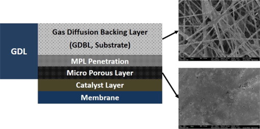
For the cathode, carbon paper-type (prepared by wet laying of chopped PAN-based carbon fibers) gas diffusion layers are the preferred solutions since they can be manufactured at high volumes (scalability) and low thickness. Chopped carbon fibers are processed to a primary carbon fiber web using a papermaking (wet-laying) technology and subsequent thermo bonding. The raw paper is then impregnated with carbonizable resins (carbonizable resins with optional addition of carbon fillers), cured and recarbonized/ graphitized. This procedure serves to adjust the porosity and to enhance electric and thermal conductivity. Different GDL backings with different filler content could be the base for the final finishing processes, such as:
- Hydrophobic treatfment with PTFE and
- Coating with a micro-porous layer (MPL)
- Sintering (thermal annealing) to bond the substrate/MPLElectrodes are the catalyst layers on the left and right side of the polymer membranes. They are considered Anodes or cathodes depending on the current that runs on their side of the membrane.
Generally, carbon plates can be used on the cathode side while metal-based GDLs, such as titanium and nickel fiber felts are more suitable for the anode side.
Another very common practice is to create a catalyst coated membrane, which is produced by applying a catalyst ink on either side of the exchange membrane.
Electrode treatments
There are various ways to treat the electrode layers. You can either apply catalyst ink on the membrane itself, or coat the Gas diffusion layer, such as LINQCELL GDL1500, with an appropriate catalyst and place it on the left and right side of the ion exchange membrane (sandwich).
MEA3 mainly refers to direct “on membrane” treatment but a catalyst ink treated GLD can also be part of this stack. Generally small stacks are considered harder to manufacture due to the longer break in period. Especially applying ink directly on the membrane can make the whole process longer and more labor intensive due to the ion exchange membrane swelling.

Catalysts
A catalyst is a substance or material that facilitates and accelerates electrochemical reactions without being consumed in the process. Catalysts play a crucial role in these electrochemical devices by reducing the activation energy required for the reactions to occur, thereby increasing the efficiency of the process.
The activity of electrocatalysts is usually measured by the current density attained at a certain overpotential or by the overpotential required to reach a certain current density. A good electrocatalyst should reach high current density using low overpotentials.
Sabatier Principle
Optimal catalytic activity is achieved when the interaction between the electrode material and the reactants and products are of intermediary strength.
The catalyst should interact not too weakly with the reactants for the surface reaction to occur, and not too strongly with the products for the desorption to happen.
Common Catalysts for Anodic Fuel Cell Reactions
Material Group | Advantage | Disadvantage |
Noble Metals (e.g., Pt, Ru) | High catalytic activity | Limited availability and high cost |
Transition Metals (e.g., Ni, Co) | Moderate cost, suitable for alkaline HOR | Lower catalytic activity compared to Pt |
Metal Oxides (e.g., MnO2) | Potential for low-cost, earth-abundant | Typically lower activity than noble metals |
Transition Metal Nitrides | High activity | Limited stability at high potentials |
Nitrogen-Doped Carbon Materials | Low cost, chemical stability | Typically requires metal or nitrogen doping |
Common Catalysts for Cathodic Fuel Cell Reactions
Material Group | Advantage | Disadvantage |
Noble Metals (e.g., Pt, Pd) | High catalytic activity | Limited availability and high cost |
Transition Metal Alloys (e.g., Pt-Co, Pt-Ni) | Enhanced activity and stability | Complex synthesis, limited control over composition |
Non-Precious Metal Catalysts (e.g., Fe-N-C, Co-N-C) | Potential for lower cost, abundance | Variability in performance, limited understanding of active sites |
Heteroatom-Doped Carbon Materials | Tunable properties, potential for lower cost | Variability in performance, active site identification |
Metal-Nitrogen-Carbon Materials | Enhanced ORR activity, stability | Complex synthesis, limited understanding of active sites |
Metal-Free Carbon Materials | Potential for lower cost, abundance | Typically lower activity than metal-containing catalysts |
Catalyst inks
Catalysts can vastly vary depending on the required outcome. But how are they applied in the system? A very easy way to go about it is to create a catalyst ink. To do so we need:
- The catalyst
- A coating/binding ionomer
We mix those two together to produce a Catalyst ink. Then we can apply this ink directly onto the membrane or on a Carbon substrate such as a Gas diffusion layer.
The following is a starting point for preparing catalyst inks based on an ink formulation designed for fuel cell catalyst layers. Please note that different ionomer content may be required depending on the application. Similarly, depending on the application and performance requirements, further optimization may be required, such as solvent composition and weight percent of solids in solution.
1. Calculate the mass of polymer, catalyst powder, and solvents required for electrode composition. As a guideline, the final ionomer to catalyst ratio should be around 10 to 25 wt%. This is heavily application dependent. Adapting existing ink formulation based on polymers of other densities based on vol% is suggested for an initial approximation. The density of Aemion+® is ~1.2 g/mL, so an ink based on 30 wt% of a ~2.0 g/mL polymer would be approximately equivalent to 18 wt% Aemion+®. It is recommended that the solvent ratio is 1:1 organic solvent or solvent mix to water, e.g. 1:1 MeOH:water. The primary alcohol can be adjusted after the polymer is dissolved in step 2. The volume of solvents required should be dictated by a final weight percent of total solids (catalyst powder + ionomer), with 1-2 wt% suggested for electrode application by spray-coating. One method of controlling drying characteristics (e.g. membrane swelling causing wrinkled catalyst layers, catalyst layer porosity, etc.) is to alter the alcohol ratio; it is strongly inadvisable to increase this ratio above 3:1

2. On a stir plate (with magnetic stirring capabilities), prepare a 3-5 wt% solution of Aemion+ and suitable low-boiling alcohol mixture from below (e.g. methanol/acetone) to dissolve the polymer. If particles are noted, pass the ionomer through a glass fiber filter to eliminate any contaminants. Reserve about 5 mL of the chosen alcohol to capture concentrated ionomer coating the glassware after dropwise addition (mentioned later).
3. Preferably in a narrow-necked glass bottle and on a stir plate capable of magnetic stirring, add the catalyst (such as Pt/C) powder followed by a stir bar and all the calculated water. Stir gently (e.g. 100 RPM) until catalyst powder is fully wetted and dispersed. Increase stir rate until a vortex begins to form but before cavitation (e.g. 400-600 RPM, heavily dependent on ink volume and stir bar size)
4. Slowly pour in the calculated alcohol, apart from the 5 mL reserve and that contained in the ionomer solution. Maintain vigorous stirring and add the alcohol/ionomer solution dropwise, visually ensuring surface accumulation of polymer is kept to a minimum. Occasionally swish to integrate catalyst particles that accumulate at the ink-bottle interface. Use the remaining 5 mL of alcohol to rinse the ionomer glassware (i.e. capture the residual polymer so calculated values for ionomer are realized) and dislodge any remaining catalyst powder from the sides of the ink bottle. Stir at moderate rate (e.g. 300 RPM) until use; a minimum of four hours is recommended. Treatment in a low-power sonication bath for 15-30 minutes after an initial 30-60 minutes of stirring may help homogeneity.
4. Slowly pour in the calculated alcohol, apart from the 5 mL reserve and that contained in the ionomer solution. Maintain vigorous stirring and add the alcohol/ionomer solution dropwise, visually ensuring surface accumulation of polymer is kept to a minimum. Occasionally swish to integrate catalyst particles that accumulate at the ink-bottle interface. Use the remaining 5 mL of alcohol to rinse the ionomer glassware (i.e. capture the residual polymer so calculated values for ionomer are realized) and dislodge any remaining catalyst powder from the sides of the ink bottle. Stir at moderate rate (e.g. 300 RPM) until use; a minimum of four hours is recommended. Treatment in a low-power sonication bath for 15-30 minutes after an initial 30-60 minutes of stirring may help homogeneity.
Role of Ionomers or Ion Exchange Polymers in Catalyst Ink Formulations
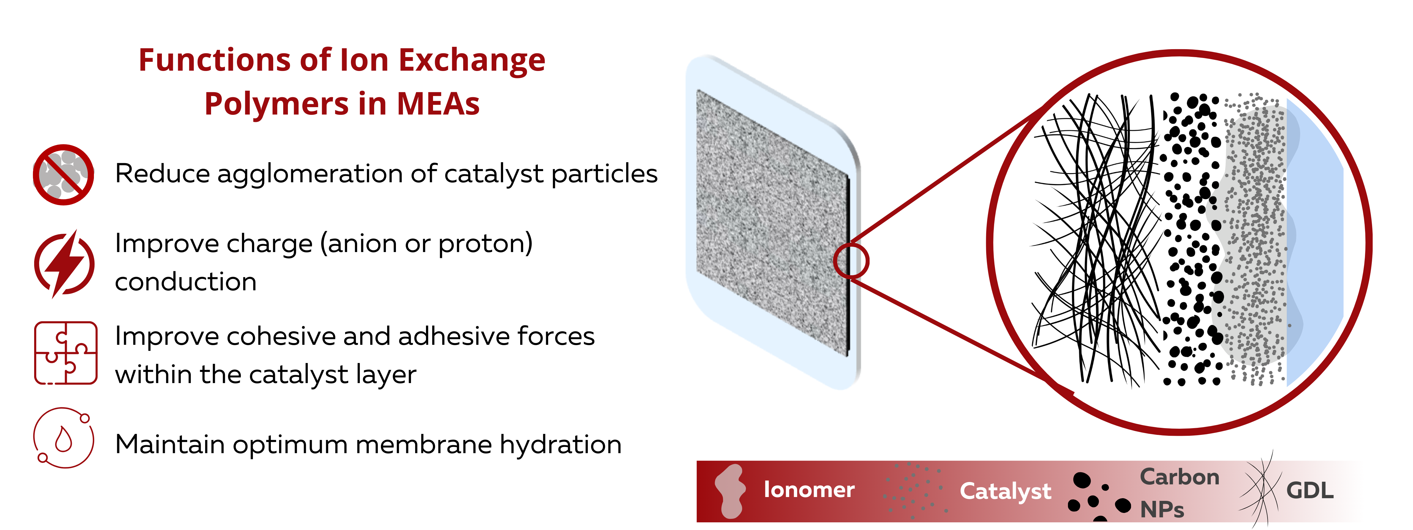
Ionomer or Ion Exchange Polymers are added into catalyst ink formulations to improve catalyst utilization. Catalyst ink formulations are typically composed of the catalyst, a solvent, and the ion exchange polymer or ionomer. The electrochemical properties, coating characteristics, and coating stability of the CL is highly dependent on the interactions of these three primary components.

Suitable solvents for High IEC polymer AP2-HNN8-00 and low IEC AP2-HNN2-00
| Solvent Type | Comments | Solubility |
| Methanol / Acetone | 50:50 (v/v) mixture. Recommended low-boiling solvent for spray coating, electrode fabrication, etc. | 1% – 10% |
| Ethanol / Acetone | 80:20 (v/v) mixture | 1% - 6% |
| DMSO | Recommended high boiling point solvent to achieve high viscosity, can cause complications with gas permeability | 1% - 10% |
| NMP, DMF | High boiling point solvents, can cause complications with gas permeability | 1% - 10% |


